Tri-Loader Stability and Load Distribution During Lifting Operations
Key Takeaways
- Maintenance standards
- Safe operation
- Field inspection guidelines
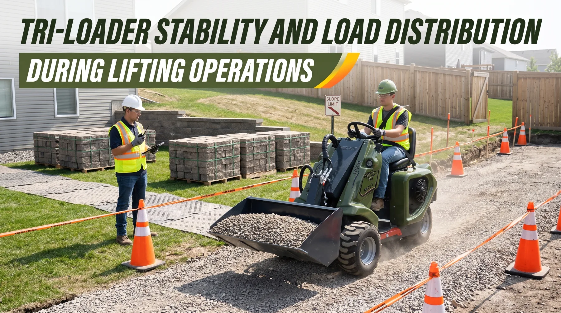
A landscaping crew uses a tri-loader to move a pallet of retaining wall blocks from the driveway to the back of a property. On the level driveway, with the forks low and the pallet tight against the carriage, the machine feels solid. Near the garden bed, the operator raises the boom to clear a low wall and starts a turn toward the drop point. The ground slopes slightly and one wheel settles into soft topsoil. The machine leans, the single support wheel goes light, and the operator stops and lowers the load just in time. The pallet weighed the same the whole way. Only its position and the ground beneath the machine changed.
Tri-loaders are compact, versatile machines built for lifting, carrying, and placing materials on construction, landscaping, agricultural, and property maintenance jobs. Their small footprint and tight turning make them useful in confined areas. That same compact design leaves less room for error when a load is raised, extended, or carried over uneven ground. Stability depends on how the machine's weight and the load's weight are distributed across its support points, and on how boom position, attachments, loading technique, and terrain change that distribution.
How Tri-Loader Weight Distribution Works
Every tri-loader rests on a set of support points, typically three wheels arranged so that two sit side by side and one sits at the opposite end. Those contact points form a triangle on the ground, often called the stability triangle. The combined center of gravity of the machine and its load must stay inside that triangle. When it moves outside any edge, the machine tips over that edge.
With the attachment empty and lowered, the center of gravity sits low and well inside the stability triangle. The engine, hydraulic components, chassis, and any counterweight are arranged to balance the boom and attachment. As soon as the operator picks up a load, the combined center of gravity moves toward the loaded end of the machine. A heavier load, or one carried farther from the machine, moves it farther. At rated capacity, the center of gravity sits closer to the edge of the triangle while still leaving a safety margin built into the manufacturer's rating. Proper operating techniques help maintain this stability. Operators should keep the load close to the machine, carry it as low as practical, avoid sudden acceleration, braking, or sharp turns, and travel at a controlled speed. Never exceed the rated lifting capacity or raise the boom unnecessarily while traveling.
The shape of the triangle matters. The base is widest where the two side-by-side wheels sit and narrowest toward the single wheel. That means a tri-loader generally resists tipping forward or backward along its length better than it resists tipping sideways near its narrow end. Sideways forces from turning, side slopes, or an off-center load push the center of gravity toward the triangle's sloped edges, where the margin is smallest. Operators who understand this geometry recognize why sharp turns and cross-slope travel deserve extra caution.
Machine configuration changes the details. Wheel spacing, track width on tracked models, counterweight options, tire type, and boom design all shift the balance. Never assume one tri-loader behaves like another, even when they look similar. The capacity chart for each model and configuration shows its approved working limits.
Key takeaway: A tri-loader stays stable only while the combined center of gravity remains inside the triangle formed by its support points. Loads move that center toward the edges, and the narrow end of the triangle offers the least protection against sideways tipping.
The Effect of Boom Position on Stability
Boom position has a stronger effect on stability than many operators realize. Raising the boom lifts the load and moves the combined center of gravity upward. Extending or lowering the boom forward moves the load farther from the machine. Both changes reduce the stability margin, and together they reduce it sharply.
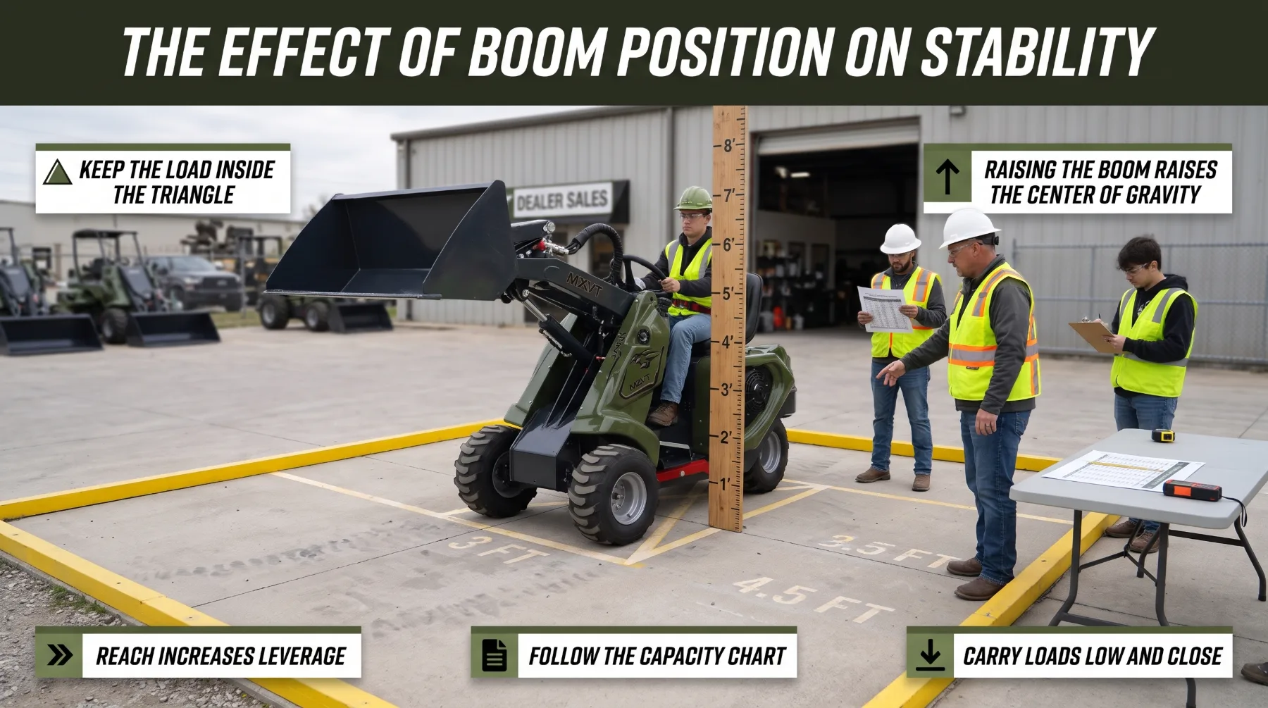
Distance from the machine works through leverage. The tipping effect of a load equals its weight multiplied by its horizontal distance from the tipping edge. Consider a 1,200-pound load held 3 feet ahead of the front wheel line. It creates 3,600 foot-pounds of tipping moment. Move that same load to 4.5 feet ahead, and the moment rises to 5,400 foot-pounds, a 50 percent increase with no change in weight. The machine's resisting weight stays the same, so the margin shrinks quickly as the load moves outward.
Height affects how the machine reacts to motion. A low center of gravity keeps the tri-loader planted when it rolls over a bump or turns. A high center of gravity makes it far more sensitive. A small dip under one wheel, a quick steering input, or a sudden stop shifts a raised load sideways or forward with much greater effect. Dynamic forces from bouncing, braking, and turning add to the static weight, so a load that sits comfortably within capacity while parked can exceed the stability margin while moving.
The safest practice is simple and consistent. Carry loads low, just high enough to clear the ground and obstacles, with the bucket rolled back or forks tilted slightly back. Raise and extend the boom only when the machine is stopped on firm, level ground at the placement point. Lower the load before traveling away. Where the capacity chart shows reduced ratings at greater height or reach, follow those figures exactly rather than the maximum headline rating.
Key takeaway: Raising the boom raises the center of gravity, and extending it increases leverage against the machine. Carry loads low and close, raise or extend the boom only when stopped on firm, level ground, and follow the capacity chart for every boom position.
Attachment Weight and Load Center
Attachments change both how much a tri-loader can lift and how stable it is while lifting. Rated operating capacity is the working limit the manufacturer approves for a specific machine and attachment. It already includes a margin below the tipping point to absorb bumps, braking, and minor load shifts. That margin is not spare capacity and should never be treated as such.
Attachment weight uses part of the machine's capacity before any material is added. Many capacity figures are published with a standard bucket. A heavier grapple, a larger bucket, or a specialty tool reduces what remains for material. For example, suppose a tri-loader carries a rating of 1,500 pounds with its standard bucket. If a grapple weighs about 300 pounds more than that bucket and sits slightly farther forward, the usable material capacity drops to roughly 1,200 pounds or less. Check the manufacturer's capacity information for each attachment rather than assuming the base rating applies.
Load center is just as important as weight. Pallet fork ratings assume a defined load center, commonly 24 inches or 500 millimeters from the fork face, depending on the manufacturer. A pallet pushed out toward the fork tips, a long bundle carried off-center, or a crate heavier at its far end all move the load center outward and reduce safe capacity. Keep pallets tight against the carriage, center loads between the forks, and spread the forks as wide as the load allows for even support.
Use only attachments approved by the manufacturer for the specific tri-loader. An unapproved attachment may fit the mounting plate yet exceed the machine's capacity, shift the load center beyond safe limits, or require hydraulic flow and pressure the machine can't supply. Never modify an attachment to extend its reach, and never add improvised counterweights to the machine to compensate for a heavy tool. Use only counterweight kits the manufacturer approves, installed exactly as instructed.
Key takeaway: Attachment weight reduces the capacity left for material, and a load center farther out reduces it further. Use only approved attachments, confirm capacity for each one, keep loads centered and tight against the carriage, and never add improvised counterweights.
Loading Technique and Material Placement
How material enters the attachment shapes how the tri-loader handles once it's loaded. A well-centered, evenly distributed load keeps the center of gravity in line with the machine. An uneven or off-center load pulls it toward one side, where the stability triangle offers the least margin.
Placement inside the attachment matters as much as total weight. Approach the pile squarely so the bucket fills evenly across its width. Avoid scooping from the corner of a pile, which loads one side of the bucket more than the other. Keep material level and below the bucket's edges so nothing falls during travel. With forks, center the load and make sure it's stable on the pallet. Strap or band loose items such as block, bags, or pipe before lifting, since a shifting load can change the machine's balance without warning.
Control the load from pickup to placement. Lift smoothly and avoid jerking the controls. Travel slowly with the load low, and stop gradually rather than braking hard. At the placement point, stop on firm, level ground, raise the load only as high as needed, and lower it gently into position. Keep people clear of the lifting, travel, and unloading areas at all times, and never allow anyone to stand or walk beneath a raised load.
Key takeaway: Estimate load weight from material density, not appearance, and fill dense material partially. Center every load, secure loose items, lift and travel smoothly, and keep people clear of the load path and beneath raised attachments.
Ground Conditions and Machine Support
Every capacity rating assumes firm, level ground. The surface beneath the tri-loader decides whether its support points stay where the stability triangle needs them. When one support point sinks, slides, or drops, the triangle tilts and the center of gravity moves toward the low side.
A three-point support base reacts quickly to uneven ground. If a single wheel drops into a hole, sinks into soft soil, or rolls over a curb, the whole machine leans immediately. Soft lawns, recent backfill, wet clay, loose gravel, sand, and frozen ground that thaws during the day can all give way under a loaded wheel. Buried tanks, septic fields, irrigation lines, and utility covers add hidden weak spots. Walk the work area before starting, mark hazards with cones or flags, and use approved ground protection mats where the surface is soft or must be protected.
Edges demand particular caution. The concentrated weight of a loaded tri-loader can collapse ground near trenches, excavations, retaining walls, ditches, and loading docks, even when the surface looks firm. Keep the machine well back from unsupported edges, and use barriers or berms where routes pass close to a drop.
Slopes multiply every stability risk. Follow the manufacturer's slope limits for the specific machine, loaded and unloaded. Travel straight up and down slopes, never across them, since cross-slope travel shifts the center of gravity toward the downhill side and the narrow edges of the stability triangle. Keep the heavy end of the machine uphill, as directed in the operator's manual. Never raise or extend a load on a slope, and never turn on an incline. If the machine begins to feel unstable, lower the load slowly and stop. Always wear the seat belt. The rollover protective structure protects the operator only when the operator stays inside it.
Key takeaway: Capacity ratings assume firm, level ground. Inspect the area for soft spots, holes, and buried hazards, stay well back from edges, travel straight up and down slopes within the manual's limits, never lift on a slope, and always wear the seat belt.
Safe Lifting and Pre-Operation Inspection
Many stability problems are visible before the engine starts. A consistent walk-around inspection catches worn, damaged, or misadjusted components that could compromise lifting control or machine support.
Begin with the tires or tracks. Check each tire for cuts, bulges, embedded objects, and correct pressure. Unequal pressures from side to side tilt the machine before it lifts anything, and an underinflated tire flexes and allows the machine to lean under load. On tracked models, check tension, rollers, and sprockets. Inspect boom pivot pins, bushings, and retainers for play, wear, or missing hardware, and look for cracked welds on the boom, attachment plate, and chassis. Check hydraulic hoses, fittings, and cylinders for abrasion, cracks, and leaks.
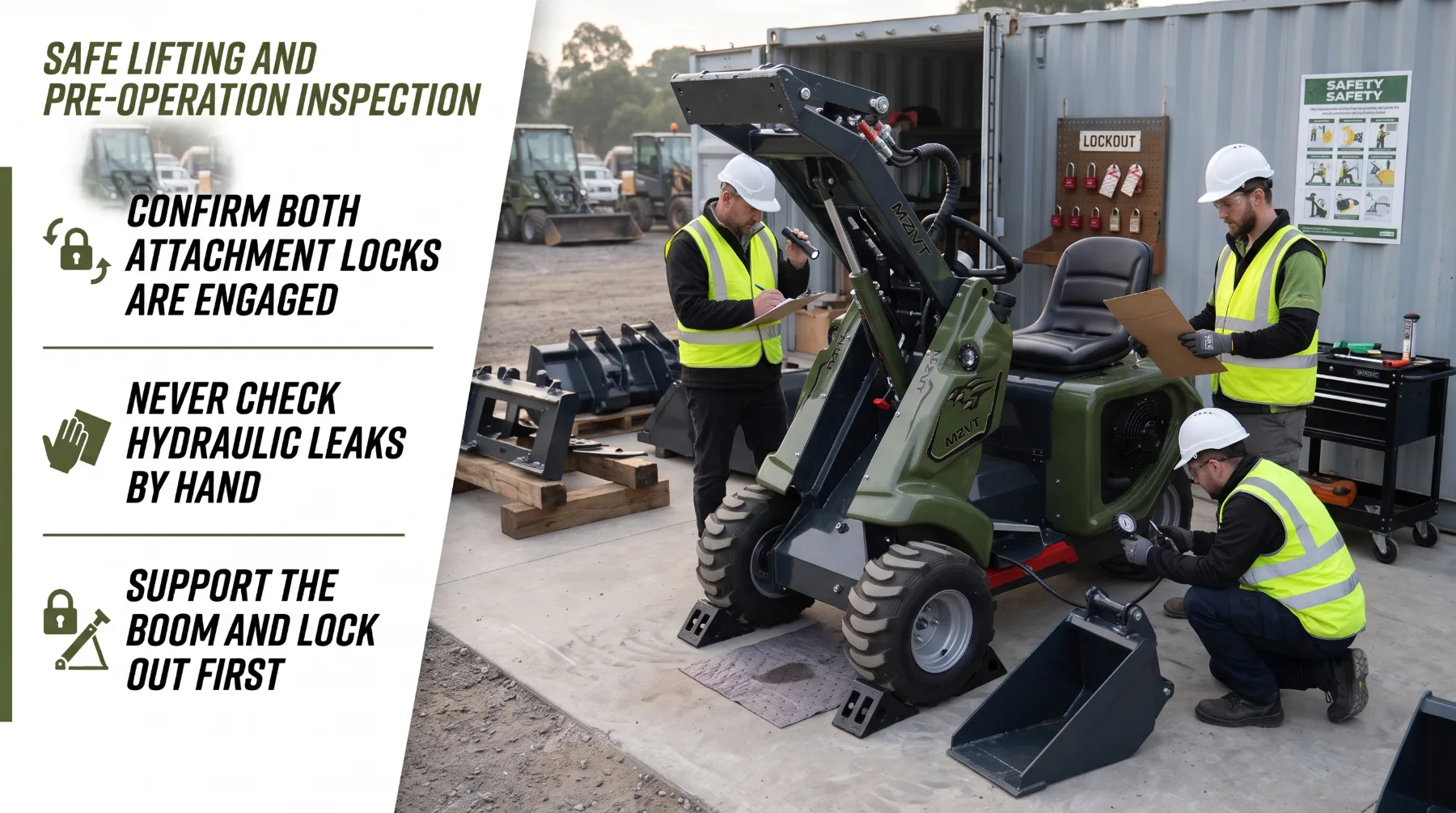
The attachment locking system deserves close attention. Confirm that the locking pins or levers are fully engaged on both sides, whether the machine uses a manual or powered quick-attach system. After every attachment change, tilt the attachment and press it gently against the ground to confirm it's secure before lifting. A partially engaged attachment can release a load or the attachment itself without warning.
Inside the operator station, test the steering, brakes, horn, lights, backup alarm, and all controls. Check the seat belt, rollover and falling object protective structures, and operator presence system. Never bypass or disable any safety device or interlock. Confirm that capacity decals are legible and that the operator understands how the installed attachment affects the machine's rating. Remove any tri-loader with faults in tires, pins, attachment locks, hydraulics, steering, brakes, or safety devices from service until a qualified technician repairs it. Only trained, authorized operators should perform lifting operations.
Leak inspection must always be done safely. Never use your hand to search for a hydraulic leak. Fluid escaping through a pinhole under pressure can penetrate skin and cause an injection injury. The wound may look minor at first, but it's a medical emergency that requires immediate surgical treatment. Use a piece of cardboard or wood, wear gloves and eye protection, and keep your face out of line with the suspected leak. If anyone is struck by escaping hydraulic fluid, get emergency medical care at once and tell medical staff it's a hydraulic injection injury.
If the boom must stay raised for access, engage the manufacturer's approved boom support device. Never work beneath a raised boom or attachment held only by hydraulics, and never rely on improvised blocking.
Key takeaway: Inspect tires or tracks, pins, hydraulics, attachment locks, controls, and safety devices every shift. Check leaks with cardboard rather than your hands, lower the attachment and lock out before service, and remove damaged machines from service until repaired.
Conclusion
Tri-loader stability depends on keeping the combined center of gravity inside the triangle formed by the machine's support points. Raising and extending the boom moves that center upward and outward, while attachment weight and load center reduce the capacity available for material. Material density, load placement, and smooth control decide how close each lift comes to the machine's limits. Ground conditions then determine whether the support points stay level and firm enough for the ratings to apply.
Frequently Asked Questions
What affects tri-loader stability during lifting?
The most important factors are load weight, load position, boom height and extension, attachment weight, and ground conditions. A heavy load held high or far from the machine moves the combined center of gravity toward the edge of the stability triangle. Soft ground, slopes, sharp turns, and sudden stops reduce the remaining margin further, so these factors must be managed together.
Does extending the boom reduce lifting stability?
Yes. Extending the boom moves the load farther from the machine, which increases its leverage against the tri-loader's resisting weight. A load moved from 3 feet to 4.5 feet ahead of the wheels creates about 50 percent more tipping effect with no change in weight. Extend the boom only when stopped on firm, level ground, and follow the capacity chart for each boom position.
Can a tri-loader lift its full rated capacity with every attachment?
No. Attachment weight uses part of the machine's capacity, and many attachments move the load center outward, which reduces safe capacity further. Rated capacity applies only to the specific attachment and configuration shown in the manufacturer's capacity information. Use only approved attachments, and confirm the rating for each one before lifting.
Why should loads be carried low during travel?
A low load keeps the combined center of gravity close to the ground and well inside the stability triangle. That makes the machine far less sensitive to bumps, turns, braking, and uneven ground. Carrying loads low also improves the operator's forward visibility. Raise the load only at the placement point, and lower it before traveling away.